Saturday, March 31, 2012

Loose cavity inner undercut release method in injection Molding

one way to release the undercut is to loose cavity, the opposite of loose cores, loose inner cavity is used to remove the undercut in the cavity area, note the image below for more details,

1 = top plate
2 = runner stripper plate
3 = cavity plate
4 = core plate
5 = locking block for loose cavity
6 = angular pin for loose cavity system
7 = loose insert cavity


some designers also say that with the inner mold cavity slider, whatever his name is, in essence, functions and works the same way. when the first opening between the top runner stripper plate (2) with the cavity plate (3) top plate will pull locking block (5) together with the angular pin (6), aided by the spring on the insert cavity, this movement causes the loose insert cavity to move straight straight to the angular movement of the pin, as a result of friction between the angular pin with a hole in the loose insert cavity.

when construction is used, ie if your product has undercut formation on a position in the cavity region, angular corners and locking block commonly used ranged from 8 to 20 degrees, above the angle can cause angular cartilage pin was broken, because the force that fought too large.
Another thing to note is the stroke, you must ensure that the stroke of movement of loose cores must be secure, which is about the length undercut products coupled with the 5-10 mm.

Loose core for ejecting undercut at injection mold


Picture above shows the loose core, or often also called slope ejectors or inclined pin, loose cores is one method to overcome the undercut on the product, particularly undercut the core position facing into the bottom (towards the sprue bush-center of mold) that undercut it can not be made simply by using slider method, part of the loose core complete with mold base include:

1. Top clamping Plate
2. stripper plate
3. cavity plate
4. core plate
6. support plate
7. top ejector plate
8. bottom ejector plate
9. bottom clamping plate
10. loose core rod
11. loose slide unit
12. bushing

for more details look at the picture below, which shows the current position of loose cores prior to the occurrence of loose core ejecting position after ejecting process, shortly after the mold is closed and the injection process, loose cores in the closed position (note the closed mold), after the injection process is complete done, at the push of ejector rod, ejector plate both upper and lower parts helped push out through the ejector, while the loose-core because it has a certain slope (generally 8-15) when driven will move slowly into center with the aid of friction on inclined leader pin bushings, so the position Loose cores are separated from the undercut product (mold opened)
Slide the unit mounted on the ejector plate is always on the top or at the bottom, and the main mover of the loose core are ejector rod simultaneously with the process of ejecting, points to consider in designing the loose core is strokes and angles used, too little angle of it can reduce the occurrence of abrasion (wear) but required a long stroke.
If angle is too large can cause the inclined pin (loose core) broken because of the occurrence of high abrasion, but required a shorter stroke. The angle that is used is usually between 8-15 0, while the stroke must be exceeded 5 mm or more to keep the loose core is certain regardless of the undercut in the product.

using mold base become locking block of slider unit

moldbase sometimes can be used for the locking block on the slider unit, this is basedon several reasons, for example, to reduce cost, by reducing the insert locking block, the other reason is required surface area for the locking block.

illustration picture above shows the angular pins are bolted to the mold base and the mold base made pocket instead of locking block,


to keep the process easy to do maintenance, should be installed oil slide plate, so when it can wear easily replaced without the need to change their plate slider block.
This model is widely used for large parts and molds with a tonnage greater than 350 tons, other advantage is the size of the mold base to be more compact and small, so the cost for the mold base can also be reduced, and if the size is smaller base can mold into tonnase also smaller

runner components of injection mold

Runner components between the two mold plate and three plate mold because there are different functions of these components, but there are several components that can be used in general without looking at the type of mold construction.


1.Runner lock pin
The main function of the runner lock pin (RLP) is an pulling runner so
the gate can be disconnected/cut from the product, RLP fitted with a straight gate position, the head planted on the top plate, while in the body mounted on the cavity plate (3) up to the top
plate (1). RLP does not move during the injection process lasts, mold base plate
moves accordance with the mold opening sequence, the tip of the runner lock pin is the part that greatly affects the success or failure of the gate runner cutting process. Greater the undercut which is the stronger the ability of RLP to attract runners from the gate, the type of plastic material also influenced for selection of RLP.
2.RLP Lock
RLP lock have function to maintain RLP order not to loose from its position, there are various ways to lock them RLP
* closed with a locating ring or sprue bush or heat insulation board.
* using a plate
* use a screw plug
3. Bushing RLP
high cycle time mold or need durability are advised to use the bushing,the benefits include easy maintenance of RLP, more resistant to wear due to friction so it's can avoid direct contact between RLP and mold plate that can caused wears, this method will shorten maintenance time.
4. Ejector runner
Only used if the runners stuck on the stripper plate mold base or stuck on the cavity mold bases, the use of the runner ejector can help the runner release from the place that was not supposed to stick. Other components are collar to the head of RLP, and change flow components

Lifting bolts hole design in injection mold

Plate transfer process occurs during the machining and assembly of mold, both for the cavity and mold base plate, especially for the plate with a weight greater than 20 kg, threaded hole necessary to facilitate the transfer process. cause may be in a mold plate having a various of machining processes with different types of machines. Base on position of hole the type of lifting bolts can divided became two, perpendicular to face, and parallel with face of plate.
perpendicular to face
beside transfer process, lifting bolts also important for lift out cavity insert from mold base, flat wide plate usually use magnet to lift from one machine to another machine or station, but if shape of plate doesn’t flat it need bolts hole to attach eye bolts, then use crane that connected to eye bolts for lifting the mold base plate or cavity plate.

Parallel with mold face.
Especially for mold base, this hole must available because transfer mold base usually use eye bolt that connected to crane, for mold base plate that use horizontal machining also use this hole to connected with crane, picture below shown mold base with metric bolt hole and eye bolts ready for transfer with crane


Runner Design in Injection Mold,

in designing the runner, first-time we must consider items that affecting  runnersize, some of which
- Volume of part, the greater the volume takes a larger diameter runners anyway.
- Weight of part, the heavier parts, it takes a larger diameter runners.
- Plastic materials, plastic materials with low viscosity, aqueous requires a smallerdiameter runner.
- Wall thickness, the thicker the greater the diameter of the runner is needed.
- Length of flow path, the longer it takes the flow of large diameter runner.


picture above shown some factor that we must consider before choosing right diameter of runner, 

Cross Section Area
various cross section area use on the market, It depends on the heat loss, machining requirement, but the most popular cross section area are circular, parabolic and trapezoid section area, picture below shows three
Diameter
to determine the diameter, based on the type of material and wall thickness, the following chart can help, for similar materials PP, PA, POM, PC, PE can use the following graph, first select the appropriate thick wall thickness and look heavy parts, and then pull the line down, the approximate diameter required will be obtained

Injection Mould Venting System, a little part of design that have big effect on part quality

venting is a small part of the mold design, on the design process also requires a very short time, perhaps only 10% or less of the total time required in designing.sometimes is frequently neglected until molding trials indicate mold inadequacies related to venting. if we understand the purpose and function of vents, it's can assists mold designer to design where clearly additional vents required.

when the cavity space injected by plastic material, automatically empty space on the cavity will be filled with plastic material, the air in the cavity will be shifted to another place, what would happen if the air can not move, the air will experience a high pressure , so the temperature rises even higher, resulting in plastic that fills the cavity will be burning, the defect is called a burn, because of the importance of venting a lot of products that fail due to not properly inject the gas vent, especially for products that have a rib that thin and tall, as compared to thick products.


source : Plastic Today


The main function of the venting is
A. compressed air release
when compressed air is not expelled from the cavity, the plastic flow is inhibited, the result will be formed on a short shot of the product
2. compressed air will produce a gas with high temperature and burn the plastic around it, resulting in a defect burn marks, the product looks like a burn, this will greatly affect the look of the product.
3. when the gas mixed with plastic, the plastic will generate an uneven structure, which will reduce the strength of the product / mold parts produced, stress concentration also common in this region, which occurs due to the plastic notch.


for more detail about effect of adequate of venting on injection mold, please see on picture below


part of venting, can divide on 2 section, land and groove, land is always contact with plastic melt, it's deep about 0.01 mm until 0.02 mm, depend on viscosity of material, relief of vent or gas land is about 1 mm until 2mm, but you must remember for rubber all the number above can't applied, gas vent on rubber material is very special, because rubber has low viscosity.
when designing the gas vent / venting on injection mould, make sure that all of the groove must have exhaust groove that connect to atsmosfer.

Cooling Layout and Cooling method between core/cavity and mold base

Cooling is most important parameter when talking about cycle time reduce, some of my friend who very interest in injection mould still confuse how to design cooling system in injection mould, before talking about optimal design, first we must be familiar with the term and design standard that will be used.


Basic Cooling Layout

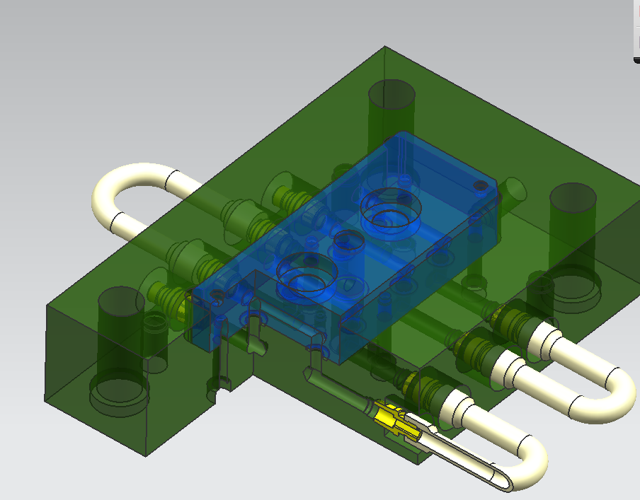
in principle, the more uniform temperature in the cavity, the better the resulting product, the more uniform and rapid heat transfer processes during the process of solidification occurs, the faster the cooling process, and of course the faster the cycle time that happened.when designing, to keep the cooling process is rapid and uniform cooling channels should be sought closer to the wall of the product, especially for regions of high and thick walls. therefore the cavity cooling channels is essential.

in the image above, is an example of basic connections cooling layout, its parts are
A. cavity colored with blue
2. green is mold base
3. yellow is cooling joint plug
4. white is hose connection to connecting cooling joint plug

on the left side of mold in above picture, we see that two pcs of cooling joint plug (yellow color) in that side, is for input and output of cooling mold base and cooling channel from the machine.

Rectangle Like Layout
depend one cooling layout is a favorite around the product, because the drilling process should be straight, then the shape is rectangle, except in the form of circular gear will be retained.

collapsible core for demolding/ejection system of internal screw undercut

one common way used in the ejection system for an internal screw is used collabsible undercut core, which requires collabsible core product generally has the undercut on the inside, for example an internal screw, pipe fittings, elbow pipe, use collabsibe core is not only on the core course , undercut the slider is also often used collabsible cores.
video below gives a simple explanation of how Collapsible cores working

http://www.die-moldtool.com/

Main Component
The three units are a Collapsible Core, center pin, and a positive collapse sleeve.

cenTer pin
The Center Pin serves to expand the segments of the Collapsible Core to their molding position and holds them at this diameter. A hole is provided inside the pin for cooling. The center pin is manufactured of a high alloy Type D-6 steel hardened to 60 to 65 Rockwell C or use SKH 51, SKD 11. Refer to the pin grinding instructions for machining directions. In use the pin must incorporate two design features. The pin must protrude beyond the face of the collapsing core segments by certain amounts. This protrusion keeps material from flowing under the face of the collapsing segments to ensure they properly collapse. A radius must be applied to the outside corner at the front of the center pin. The sharp edge resulting from cutting the pin to length will gall and subsequently destroy the inside surfaces of the collapsing core segments
collapsible core
The Collapsible Core is manufactured from A.I.S.I. Type A-2 steel hardened to 51 to 57 Rockwell C. It is designed to collapse independently when the center pin is withdrawn. The fit between segments is controlled to permit flash free molding. The location of the core on its pin is critical. The distance between the back of the core flange and the front of the center pin flange (Head Space) is critical and must be maintained.
If the Head Space (1.938 ±.005 on a CC 202 PC) is not maintained, unsatisfactory operation will result, or the core may be permanently damaged.
posiTive collapse sleeve
The Positive Collapse Sleeve (PC sleeve) is designed to function when the Collapsible Core fails to collapse independently upon withdrawal of the center pin. In normal operation, the PC sleeve is not functioning. It is essential to have such a unit for maximum safety and reliability in automatic and semi-automatic operation. Under no circumstances should a mold be placed into automatic operation without the use of the PC sleeve.

picture above shown collapsible core and the component, detail explanation about CC we can find it in DME standard part http://www.dme.net/dme/resources/FAQs/collapse_cores.html

Saturday, August 20, 2011

Drill Size Chart

The drill size chart provides a list of standard size drill bits in several measurement systems, including fractional, metric, wire gauge number, and letter. The decimal equivalents of the diameters are shown in both English and Metric units. Fractional sizes are measured in inches, while metric sizes are measured in millimeters. The wire gauge and letter systems refer to tool diameters that increase as the wire gauge decreases from #107 to #1 and then continues from A to Z. The drill size chart contains tools up to 1.5 inches in diameter, but larger tools are also commonly used.


Drill size Diameter (in) Diameter (mm)
#1070.00190.0483
0.05 mm0.00200.0500
#1060.00230.0584
#1050.00270.0686
#1040.00310.0787
#1030.00350.0889
#1020.00390.0991
0.1 mm0.00390.1000
#1010.00430.1092
#1000.00470.1194
#990.00510.1295
#980.00550.1397
#970.00590.1499
#960.00630.1600
#950.00670.1702
#940.00710.1803
#930.00750.1905
0.2 mm0.00790.2000
#920.00790.2007
#910.00830.2108
#900.00870.2210
#890.00910.2311
#880.00950.2413
#870.01000.2540
#860.01050.2667
#850.01100.2794
#840.01150.2921
0.3 mm0.01180.3000
#830.01200.3048
#820.01250.3175
#810.01300.3302
#800.01350.3429
#790.01450.3680
1/64 in0.01560.3969
0.4 mm0.01580.4000
#780.01600.4064
#770.01800.4572
0.5 mm0.01970.5000
#760.02000.5080
#750.02100.5334
#740.02250.5715
0.6 mm0.02360.6000
#730.02400.6096
#720.02500.6350
#710.02600.6604
0.7 mm0.02760.7000
#700.02800.7112
#690.02920.7417
#680.03100.7874
1/32 in0.03130.7938
0.8 mm0.03150.8000
#670.03200.8128
#660.03300.8382
#650.03500.8890
0.9 mm0.03540.9000
#640.03600.9144
#630.03700.9398
#620.03800.9652
#610.03900.9906
1 mm0.03941.0000
#600.04001.0160
#590.04101.0414
#580.04201.0668
#570.04301.0922
1.1 mm0.04331.1000
#560.04651.1811
3/64 in0.04691.1906
1.2 mm0.04721.2000
1.3 mm0.05121.3000
#550.05201.3208
#540.05501.3970
1.4 mm0.05511.4000
1.5 mm0.05911.5000
#530.05951.5113
1/16 in0.06251.5875
1.6 mm0.06301.6000
#520.06351.6129
1.7 mm0.06691.7000
#510.06701.7018
#500.07001.7780
1.8 mm0.07091.8000
#490.07301.8542
1.9 mm0.07481.9000
#480.07601.9304
5/64 in0.07811.9844
#470.07851.9939
2 mm0.07872.0000
#460.08102.0574
#450.08202.0828
2.1 mm0.08272.1000
#440.08602.1844
2.2 mm0.08662.2000
#430.08902.2606
2.3 mm0.09062.3000
#420.09352.3749
3/32 in0.09382.3813
2.4 mm0.09452.4000
#410.09602.4384
#400.09802.4892
2.5 mm0.09842.5000
#390.09952.5273
#380.10152.5781
2.6 mm0.10242.6000
#370.10402.6416
2.7 mm0.10632.7000
#360.10652.7051
7/64 in0.10942.7781
#350.11002.7940
2.8 mm0.11022.8000
#340.11102.8194
#330.11302.8702
2.9 mm0.11422.9000
#320.11602.9464
3 mm0.11813.0000
#310.12003.0480
3.1 mm0.12213.1000
1/8 in0.12503.1750
3.2 mm0.12603.2000
#300.12853.2639
3.3 mm0.12993.3000
3.4 mm0.13393.4000
#290.13603.4544
3.5 mm0.13783.5000
#280.14053.5687
9/64 in0.14063.5719
3.6 mm0.14173.6000
#270.14403.6576
3.7 mm0.14573.7000
#260.14703.7338
#250.14953.7973
3.8 mm0.14963.8000
#240.15203.8608
3.9 mm0.15353.9000
#230.15403.9116
5/32 in0.15633.9688
#220.15703.9878
4 mm0.15754.0000
#210.15904.0386
#200.16104.0894
4.1 mm0.16144.1000
4.2 mm0.16544.2000
#190.16604.2164
4.3 mm0.16934.3000
#180.16954.3053
11/64 in0.17194.3656
#170.17304.3942
4.4 mm0.17324.4000
#160.17704.4958
4.5 mm0.17724.5000
#150.18004.5720
4.6 mm0.18114.6000
#140.18204.6228
#130.18504.6990
4.7 mm0.18504.7000
3/16 in0.18754.7625
4.8 mm0.18904.8000
#120.18904.8006
#110.19104.8514
4.9 mm0.19294.9000
#100.19354.9149
#90.19604.9784
5 mm0.19695.0000
#80.19905.0546
5.1 mm0.20085.1000
#70.20105.1054
13/64 in0.20315.1594
#60.20405.1816
5.2 mm0.20475.2000
#50.20555.2197
5.3 mm0.20875.3000
#40.20905.3086
5.4 mm0.21265.4000
#30.21305.4102
5.5 mm0.21655.5000
7/32 in0.21885.5563
5.6 mm0.22055.6000
#20.22105.6134
5.7 mm0.22445.7000
#10.22805.7912
5.8 mm0.22845.8000
5.9 mm0.23235.9000
A0.23405.9436
15/64 in0.23445.9531
6 mm0.23626.0000
B0.23806.0452
6.1 mm0.24026.1000
C0.24206.1468
6.2 mm0.24416.2000
D0.24606.2484
6.3 mm0.24806.3000
1/4 in0.25006.3500
E0.25006.3500
6.4 mm0.25206.4000
6.5 mm0.25596.5000
F0.25706.5278
6.6 mm0.25986.6000
G0.26106.6294
6.7 mm0.26386.7000
17/64 in0.26566.7469
H0.26606.7564
6.8 mm0.26776.8000
6.9 mm0.27176.9000
I0.27206.9088
7 mm0.27567.0000
J0.27707.0358
7.1 mm0.27957.1000
K0.28107.1374
9/32 in0.28137.1438
7.2 mm0.28357.2000
7.3 mm0.28747.3000
L0.29007.3660
7.4 mm0.29137.4000
M0.29507.4930
7.5 mm0.29537.5000
19/64 in0.29697.5406
7.6 mm0.29927.6000
N0.30207.6708
7.7 mm0.30327.7000
7.8 mm0.30717.8000
7.9 mm0.31107.9000
5/16 in0.31257.9375
8 mm0.31508.0000
O0.31608.0264
8.1 mm0.31898.1000
8.2 mm0.32288.2000
P0.32308.2042
8.3 mm0.32688.3000
21/64 in0.32818.3344
8.4 mm0.33078.4000
Q0.33208.4328
8.5 mm0.33478.5000
8.6 mm0.33868.6000
R0.33908.6106
8.7 mm0.34258.7000
11/32 in0.34388.7313
8.8 mm0.34658.8000
S0.34808.8392
8.9 mm0.35048.9000
9 mm0.35439.0000
T0.35809.0932
9.1 mm0.35839.1000
23/64 in0.35949.1281
9.2 mm0.36229.2000
9.3 mm0.36619.3000
U0.36809.3472
9.4 mm0.37019.4000
9.5 mm0.37409.5000
3/8 in0.37509.5250
V0.37709.5758
9.6 mm0.37809.6000
9.7 mm0.38199.7000
9.8 mm0.38589.8000
W0.38609.8044
9.9 mm0.38989.9000
25/64 in0.39069.9219
10 mm0.393710.0000
X0.397010.0838
Y0.404010.2616
13/32 in0.406310.3188
Z0.413010.4902
10.5 mm0.413410.5000
27/64 in0.421910.7156
11 mm0.433111.0000
7/16 in0.437511.1125
11.5 mm0.452811.5000
29/64 in0.453111.5094
15/32 in0.468811.9063
12 mm0.472412.0000
31/64 in0.484412.3031
12.5 mm0.492112.5000
1/2 in0.500012.7000
13 mm0.511813.0000
33/64 in0.515613.0969
17/32 in0.531313.4938
13.5 mm0.531513.5000
35/64 in0.546913.8906
14 mm0.551214.0000
9/16 in0.562514.2875
14.5 mm0.570914.5000
37/64 in0.578114.6844
15 mm0.590615.0000
19/32 in0.593815.0813
39/64 in0.609415.4781
15.5 mm0.610215.5000
5/8 in0.625015.8750
16 mm0.629916.0000
41/64 in0.640616.2719
16.5 mm0.649616.5000
17 mm0.669317.0000
43/64 in0.671917.0656
11/16 in0.687517.4625
17.5 mm0.689017.5000
45/64 in0.703117.8594
18 mm0.708718.0000
23/32 in0.718818.2563
18.5 mm0.728418.5000
47/64 in0.734418.6531
19 mm0.748019.0000
3/4 in0.750019.0500
49/64 in0.765619.4469
19.5 mm0.767719.5000
25/32 in0.781319.8438
20 mm0.787420.0000
51/64 in0.796920.2406
20.5 mm0.807120.5000
13/16 in0.812520.6375
21 mm0.826821.0000
53/64 in0.828121.0344
27/32 in0.843821.4313
21.5 mm0.846521.5000
55/64 in0.859421.8281
22 mm0.866122.0000
7/8 in0.875022.2250
22.5 mm0.885822.5000
57/64 in0.890622.6219
23 mm0.905523.0000
29/32 in0.906323.0188
21/23 in0.913023.1913
59/64 in0.921923.4156
23.5 mm0.925223.5000
15/16 in0.937523.8125
24 mm0.944924.0000
61/64 in0.953124.2094
24.5 mm0.964624.5000
31/32 in0.968824.6063
25 mm0.984325.0000
63/64 in0.984425.0031
1 in1.000025.4000
25.5 mm1.003925.5000
1 1/64 in1.015625.7969
26 mm1.023626.0000
1 1/32 in1.031326.1938
26.5 mm1.043326.5000
1 3/64 in1.046926.5906
1 1/16 in1.062526.9875
27 mm1.063027.0000
1 5/64 in1.078127.3844
27.5 mm1.082727.5000
1 3/32 in1.093827.7813
28 mm1.102428.0000
1 7/64 in1.109428.1781
28.5 mm1.122128.5000
1 1/8 in1.125028.5750
1 9/64 in1.140628.9719
29 mm1.141729.0000
1 5/32 in1.156329.3688
29.5 mm1.161429.5000
1 11/64 in1.171929.7656
30 mm1.181130.0000
1 3/16 in1.187530.1625
30.5 mm1.200830.5000
1 13/64 in1.203130.5594
1 7/32 in1.218830.9563
31 mm1.220531.0000
1 15/64 in1.234431.3531
31.5 mm1.240231.5000
1 1/4 in1.250031.7500
32 mm1.259832.0000
1 17/64 in1.265632.1469
32.5 mm1.279532.5000
1 9/32 in1.281332.5438
1 19/64 in1.296932.9406
33 mm1.299233.0000
1 5/16 in1.312533.3375
33.5 mm1.318933.5000
1 21/64 in1.328133.7344
34 mm1.338634.0000
1 11/32 in1.343834.1313
34.5 mm1.358334.5000
1 23/64 in1.359434.5281
1 3/8 in1.375034.9250
35 mm1.378035.0000
1 25/64 in1.390635.3219
35.5 mm1.397635.5000
1 13/32 in1.406335.7188
36 mm1.417336.0000
1 27/64 in1.421936.1156
36.5 mm1.437036.5000
1 7/16 in1.437536.5125
1 29/64 in1.453136.9094
37 mm1.456737.0000
1 15/32 in1.468837.3063
37.5 mm1.476437.5000
1 31/64 in1.484437.7031
38 mm1.496138.0000
1 1/2 in1.500038.1000

Tap Size Chart

The tap size chart provides a list of standard size taps, specifying the diameter and thread spacing, for fractional, metric, and screw sizes. The decimal equivalents of the diameters are shown in both English and Metric units. Fractional sizes are listed in inches, while metric sizes are listed in millimeters following the letter "M". A screw size number corresponds to a diameter which is larger for a higher screw size. The thread spacing, which may be coarse or fine, is listed after the diameter. In the fractional and screw size systems, the thread count is used, measured in threads per inch. The metric system uses the thread pitch, which is the distance between threads, measured in millimeters. For each thread count, the equivalent thread pitch is provided and for metric taps, the approximate thread count is shown based on the pitch. Lastly, the recommended tap drill size is provided for each standard tap size. This size drill bit should be used for drilling the initial hole that will then be tapped.
 
Tap size Diameter (in) Diameter (mm) Thread count (TPI) Thread pitch (mm) Tap drill size
#0000-1600.02100.53341600.1591/64 in
#000-1200.03400.86361200.212#71
M1x0.20.03941.0000~1270.2000.8 mm
M1x0.250.03941.0000~1020.2500.75 mm
M1.1x0.250.04331.1000~1020.2500.85 mm
M1.1x0.20.04331.1000~1270.2000.9 mm
#00-900.04701.1938900.282#65
M1.2x0.20.04721.2000~1270.2001 mm
M1.2x0.250.04721.2000~1020.2500.95 mm
M1.4x0.20.05511.4000~1270.2001.2 mm
M1.4x0.30.05511.4000~850.3001.1 mm
#0-800.06001.5240800.3183/64 in
M1.6x0.20.06301.6000~1270.2001.4 mm
M1.6x0.350.06301.6000~730.3501.25 mm
M1.8x0.20.07091.8000~1270.2001.6 mm
M1.8x0.350.07091.8000~730.3501.45 mm
#1-640.07301.8542640.397#52
#1-720.07301.8542720.353#53
M2x0.250.07872.0000~1020.2501.75 mm
M2x0.40.07872.0000~640.4001.6 mm
#2-560.08602.1844560.454#50
#2-640.08602.1844640.397#50
M2.2x0.250.08662.2000~1020.2501.95 mm
M2.2x0.450.08662.2000~570.4501.75 mm
M2.5x0.350.09842.5000~730.3502.1 mm
M2.5x0.450.09842.5000~570.4502.05 mm
#3-480.09902.5146480.529#47
#3-560.09902.5146560.454#45
#4-400.11202.8448400.635#43
#4-480.11202.8448480.529#42
M3x0.350.11813.0000~730.3502.6 mm
M3x0.50.11813.0000~510.5002.5 mm
#5-400.12503.1750400.635#39
#5-440.12503.1750440.577#37
M3.5x0.350.13783.5000~730.3503.1 mm
M3.5x0.60.13783.5000~430.6002.9 mm
#6-320.13803.5052320.794#36
#6-400.13803.5052400.635#33
M4x0.350.15754.0000~730.3503.6 mm
M4x0.50.15754.0000~510.5003.5 mm
M4x0.70.15754.0000~370.7003.3 mm
#8-320.16404.1656320.794#29
#8-360.16404.1656360.706#29
M4.5x0.50.17724.5000~510.5004 mm
M4.5x0.750.17724.5000~340.7503.8 mm
#10-320.19004.8260320.794#21
#10-240.19004.8260241.058#25
M5x0.50.19695.0000~510.5004.5 mm
M5x0.80.19695.0000~320.8004.2 mm
#12-240.21605.4864241.058#17
#12-280.21605.4864280.907#15
M5.5x0.50.21655.5000~510.5005 mm
M6x0.50.23626.0000~510.5005.5 mm
M6x0.750.23626.0000~340.7505.2 mm
M6x10.23626.0000~261.0005 mm
1/4-200.25006.3500201.270#7
1/4-280.25006.3500280.907#3
M7x0.750.27567.0000~340.7506.2 mm
M7x10.27567.0000~261.0006 mm
5/16-180.31257.9375181.411F
5/16-240.31257.9375241.058I
M8x0.50.31508.0000~510.5007.5 mm
M8x0.750.31508.0000~340.7507.2 mm
M8x10.31508.0000~261.0007 mm
M8x1.250.31508.0000~211.2506.8 mm
M9x0.750.35439.0000~340.7508.2 mm
M9x10.35439.0000~261.0008 mm
M9x1.250.35439.0000~211.2507.8 mm
3/8-240.37509.5250241.058Q
3/8-160.37509.5250161.5885/16 in
M10x0.750.393710.0000~340.7509.2 mm
M10x1.50.393710.0000~171.5008.5 mm
M10x1.250.393710.0000~211.2508.8 mm
M10x10.393710.0000~261.0009 mm
M11x0.750.433111.0000~340.75010.2 mm
M11x10.433111.0000~261.00010 mm
M11x1.50.433111.0000~171.5009.5 mm
7/16-140.437511.1125141.814U
7/16-200.437511.1125201.27025/64 in
M12x1.50.472412.0000~171.50010.5 mm
M12x1.750.472412.0000~151.75010.2 mm
M12x0.750.472412.0000~340.75011.25 mm
M12x10.472412.0000~261.00011 mm
M12x1.250.472412.0000~211.25010.8 mm
1/2-200.500012.7000201.27029/64 in
1/2-130.500012.7000131.95427/64 in
M14x1.50.551214.0000~171.50012.5 mm
M14x1.250.551214.0000~211.25012.8 mm
M14x10.551214.0000~261.00013 mm
M14x20.551214.0000~132.00012 mm
9/16-180.562514.2875181.41133/64 in
9/16-120.562514.2875122.11731/64 in
M15x10.590615.0000~261.00014 mm
M15x1.50.590615.0000~171.50013.5 mm
5/8-180.625015.8750181.41137/64 in
5/8-110.625015.8750112.30917/32 in
M16x20.629916.0000~132.00014 mm
M16x1.50.629916.0000~171.50014.5 mm
M16x10.629916.0000~261.00015 mm
M17x10.669317.0000~261.00016 mm
M17x1.50.669317.0000~171.50015.5 mm
M18x2.50.708718.0000~112.50015.5 mm
M18x10.708718.0000~261.00017 mm
M18x1.50.708718.0000~171.50016.5 mm
M18x20.708718.0000~132.00016 mm
3/4-160.750019.0500161.58811/16 in
3/4-100.750019.0500102.54021/32 in
M20x20.787420.0000~132.00018 mm
M20x1.50.787420.0000~171.50018.5 mm
M20x10.787420.0000~261.00019 mm
M20x2.50.787420.0000~112.50017.5 mm
M22x20.866122.0000~132.00020 mm
M22x1.50.866122.0000~171.50020.5 mm
M22x10.866122.0000~261.00021 mm
M22x2.50.866122.0000~112.50019.5 mm
7/8-90.875022.225092.82249/64 in
7/8-140.875022.2250141.81413/16 in
M24x30.944924.0000~93.00021 mm
M24x10.944924.0000~261.00023 mm
M24x1.50.944924.0000~171.50022.5 mm
M24x20.944924.0000~132.00022 mm
M25x20.984325.0000~132.00023 mm
M25x10.984325.0000~261.00024 mm
M25x1.50.984325.0000~171.50023.5 mm
1-141.000025.4000141.81415/16 in
1-81.000025.400083.1757/8 in
M26x1.51.023626.0000~171.50024.5 mm
M27x1.51.063027.0000~171.50025.5 mm
M27x31.063027.0000~93.00024 mm
M27x11.063027.0000~261.00026 mm
M27x21.063027.0000~132.00025 mm
M28x21.102428.0000~132.00026 mm
M28x11.102428.0000~261.00027 mm
M28x1.51.102428.0000~171.50026.5 mm
1 1/8-121.125028.5750122.1171 3/64 in
1 1/8-71.125028.575073.62963/64 in
M30x1.51.181130.0000~171.50028.5 mm
M30x3.51.181130.0000~83.50026.5 mm
M30x21.181130.0000~132.00028 mm
1 1/4-121.250031.7500122.1171 11/64 in
1 1/4-71.250031.750073.6291 7/64 in
M33x21.299233.0000~132.00031 mm
M33x3.51.299233.0000~83.50029.5 mm
M36x31.417336.0000~93.00033 mm
M36x41.417336.0000~74.00032 mm
1 1/2 -121.500038.1000122.1171 27/64 in
1 1/2-61.500038.100064.2331 11/32 in
M39x41.535439.0000~74.00035 mm
M39x31.535439.0000~93.00036 mm
M42x4.51.653542.0000~64.50037.5 mm
1 3/4-121.750044.4500122.1171 43/64 in
1 3/4-51.750044.450055.0801 35/64 in
M45x4.51.771745.0000~64.50040.5 mm
M48x51.889848.0000~65.00043 mm
2-122.000050.8000122.1171 59/64 in
2-4 1/22.000050.80004.55.6441 25/32 in
M52x52.047252.0000~65.00047 mm
M56x5.52.204756.0000~55.50050.5 mm
M60x5.52.362260.0000~55.50054.5 mm
M64x62.519764.0000~56.00058 mm
M68x62.677268.0000~56.00062 mm

Stretch Forming

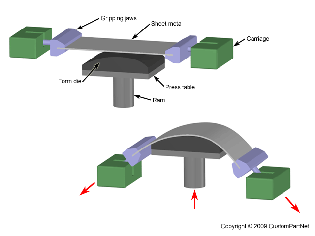
Stretch forming is a metal forming process in which a piece of sheet metal is stretched and bent simultaneously over a die in order to form large contoured parts. Stretch forming is performed on a stretch press, in which a piece of sheet metal is securely gripped along its edges by gripping jaws. The gripping jaws are each attached to a carriage that is pulled by pneumatic or hydraulic force to stretch the sheet. The tooling used in this process is a stretch form block, called a form die, which is a solid contoured piece against which the sheet metal will be pressed. The most common stretch presses are oriented vertically, in which the form die rests on a press table that can be raised into the sheet by a hydraulic ram. As the form die is driven into the sheet, which is gripped tightly at its edges, the tensile forces increase and the sheet plastically deforms into a new shape. Horizontal stretch presses mount the form die sideways on a stationary press table, while the gripping jaws pull the sheet horizontally around the form die.
 
Stretch Forming

Stretch formed parts are typically large and possess large radius bends. The shapes that can be produced vary from a simple curved surface to complex non-uniform cross sections. Stretch forming is capable of shaping parts with very high accuracy and smooth surfaces. Ductile materials are preferable, the most commonly used being aluminum, steel, and titanium. Typical stretch formed parts are large curved panels such as door panels in cars or wing panels on aircraft. Other stretch formed parts can be found in window frames and enclosures.

Deep Drawing

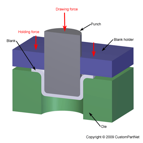
Deep drawing is a metal forming process in which sheet metal is stretched into the desired part shape. A tool pushes downward on the sheet metal, forcing it into a die cavity in the shape of the desired part. The tensile forces applied to the sheet cause it to plastically deform into a cup-shaped part. Deep drawn parts are characterized by a depth equal to more than half of the diameter of the part. These parts can have a variety of cross sections with straight, tapered, or even curved walls, but cylindrical or rectangular parts are most common. Deep drawing is most effective with ductile metals, such as aluminum, brass, copper, and mild steel. Examples of parts formed with deep drawing include automotive bodies and fuel tanks, cans, cups, kitchen sinks, and pots and pans.

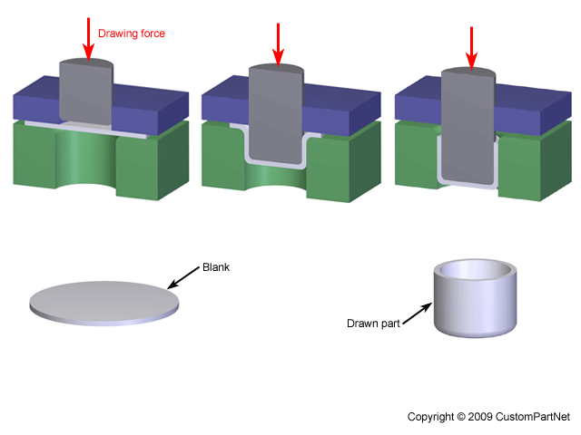
The deep drawing process requires a blank, blank holder, punch, and die. The blank is a piece of sheet metal, typically a disc or rectangle, which is pre-cut from stock material and will be formed into the part. The blank is clamped down by the blank holder over the die, which has a cavity in the external shape of the part. A tool called a punch moves downward into the blank and draws, or stretches, the material into the die cavity. The movement of the punch is usually hydraulically powered to apply enough force to the blank. Both the die and punch experience wear from the forces applied to the sheet metal and are therefore made from tool steel or carbon steel. The process of drawing the part sometimes occurs in a series of operations, called draw reductions. In each step, a punch forces the part into a different die, stretching the part to a greater depth each time. After a part is completely drawn, the punch and blank holder can be raised and the part removed from the die. The portion of the sheet metal that was clamped under the blank holder may form a flange around the part that can be trimmed off.

 
Deep Drawing

 
Deep Drawing Sequence

Spinning

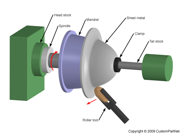
Spinning, sometimes called spin forming, is a metal forming process used to form cylindrical parts by rotating a piece of sheet metal while forces are applied to one side. A sheet metal disc is rotated at high speeds while rollers press the sheet against a tool, called a mandrel, to form the shape of the desired part. Spun metal parts have a rotationally symmetric, hollow shape, such as a cylinder, cone, or hemisphere. Examples include cookware, hubcaps, satellite dishes, rocket nose cones, and musical instruments.

Spinning is typically performed on a manual or CNC lathe and requires a blank, mandrel, and roller tool. The blank is the disc-shaped piece of sheet metal that is pre-cut from sheet stock and will be formed into the part. The mandrel is a solid form of the internal shape of the part, against which the blank will be pressed. For more complex parts, such as those with reentrant surfaces, multi-piece mandrels can be used. Because the mandrel does not experience much wear in this process, it can be made from wood or plastic. However, high volume production typically utilizes a metal mandrel. The mandrel and blank are clamped together and secured between the headstock and tailstock of the lathe to be rotated at high speeds by the spindle. While the blank and mandrel rotate, force is applied to the sheet by a tool, causing the sheet to bend and form around the mandrel. The tool may make several passes to complete the shaping of the sheet. This tool is usually a roller wheel attached to a lever. Rollers are available in different diameters and thicknesses and are usually made from steel or brass. The rollers are inexpensive and experience little wear allowing for low volume production of parts.

 
Spinning Lathe

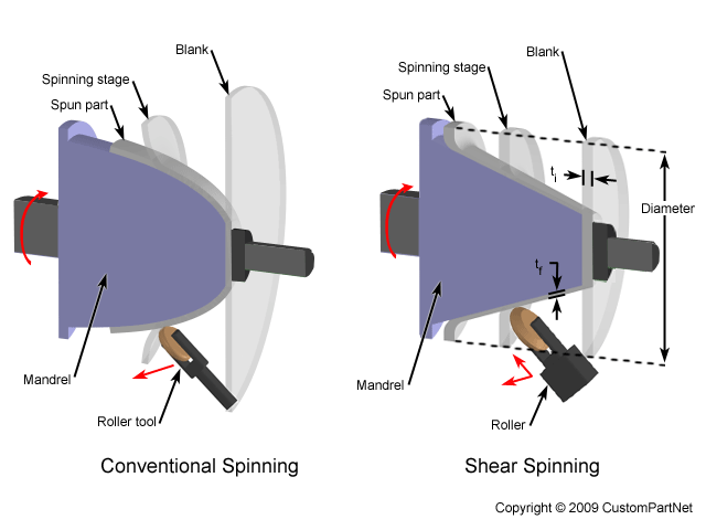
There are two distinct spinning methods, referred to as conventional spinning and shear spinning. In conventional spinning, the roller tool pushes against the blank until it conforms to the contour of the mandrel. The resulting spun part will have a diameter smaller than the blank, but will maintain a constant thickness. In shear spinning, the roller not only bends the blank against the mandrel, it also applies a downward force while it moves, stretching the material over the mandrel. By doing so, the outer diameter of the spun part will remain equal to the original blank diameter, but the thickness of the part walls will be thinner.

 
Conventional Spinning vs. Shear Spinning

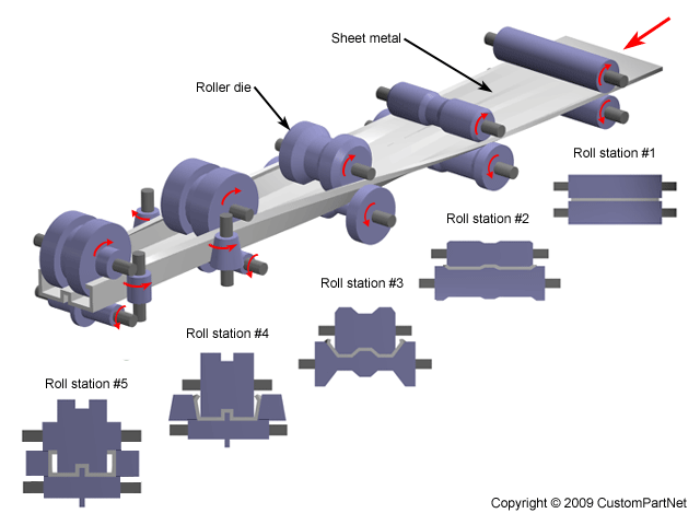
Roll forming

sRoll forming, sometimes spelled rollforming, is a metal forming process in which sheet metal is progressively shaped through a series of bending operations. The process is performed on a roll forming line in which the sheet metal stock is fed through a series of roll stations. Each station has a roller, referred to as a roller die, positioned on both sides of the sheet. The shape and size of the roller die may be unique to that station, or several identical roller dies may be used in different positions. The roller dies may be above and below the sheet, along the sides, at an angle, etc. As the sheet is forced through the roller dies in each roll station, it plastically deforms and bends. Each roll station performs one stage in the complete bending of the sheet to form the desired part. The roller dies are lubricated to reduce friction between the die and the sheet, thus reducing the tool wear. Also, lubricant can allow for a higher production rate, which will also depend on the material thickness, number of roll stations, and radius of each bend. The roll forming line can also include other sheet metal fabrication operations before or after the roll forming, such as punching or shearing.

 
Roll Forming Line

The roll forming process can be used to form a sheet into a wide variety of cross-section profiles. An open profile is most common, but a closed tube-like shape can be created as well. Because the final form is achieved through a series of bends, the part does not require a uniform or symmetric cross-section along its length. Roll forming is used to create very long sheet metal parts with typical widths of 1-20 inches and thicknesses of 0.004-0.125 inches. However wider and thicker sheets can be formed, some up to 5 ft. wide and 0.25 inches thick. The roll forming process is capable of producing parts with tolerances as tight as ±0.005 inches. Typical roll formed parts include panels, tracks, shelving, etc. These parts are commonly used in industrial and commercial buildings for roofing, lighting, storage units, and HVAC applications.