Showing posts with label Sheet Metal Cutting. Show all posts

Saturday, August 20, 2011

Water jet cutting

Water jet cutting uses a high velocity stream of water to cut through sheet metal. The water typically contains abrasive particles to wear the material and travels in a narrow jet at high speeds, around 2000 ft/sec. As a result, the water jet applies very high pressure (around 60,000 psi) to the material at the cut location and quickly erodes the material. The position of the water jet is typically computer controlled to follow the desired cutting path.

Water jet cutting can be used to cut nearly any 2D shape out of sheet metal. The width of the cuts is typically between 0.002 and 0.06 inches and the edges are of good quality. Because no burrs are formed, secondary finishing is usually not required. Also, by not using heat to melt the material, like laser and plasma cutting, heat distortion is not a concern.

Plasma cutting

Plasma cutting uses a focused stream of ionized gas, or plasma, to cut through sheet metal. The plasma flows at extremely high temperatures and high velocity and is directed toward the cutting location by a nozzle. When the plasma contacts the surface below, the metal melts into a molten state. The molten metal is then blown away from the cut by the flow of ionized gas from the nozzle. The position of the plasma stream relative to the sheet is precisely controlled to follow the desired cutting path.

Plasma cutting is performed with a plasma torch that may be hand held or, more commonly, computer controlled. CNC (computer numerically controlled) plasma cutting machines enable complex and precision cuts to made. In either type of plasma torch, the flow of plasma is created by first blowing an inert gas at high speed though a nozzle pointed at the cutting surface. An electrical arc, formed through the flow of gas, ionizes the gas into plasma. The nozzle then focuses the flow of plasma onto the cut location. As with laser cutting, this process does not require any physical tooling which reduces initial costs and allows for cost effective low volume production.

The capabilities of plasma cutting vary slightly from laser cutting. While both processes are able to cut nearly any 2D shape out of sheet metal, plasma cutting cannot achieve the same level of precision and finish. Edges may be rough, especially with thicker sheets, and the surface of the material will have an oxide layer that can be removed with secondary processes. However, plasma cutting is capable of cutting through far thicker sheets than laser cutting and is often used for workpieces beyond sheet metal.

Laser beam cutting

Laser cutting uses a high powered laser to cut through sheet metal. A series of mirrors and lenses direct and focus a high-energy beam of light onto the surface of the sheet where it is to be cut. When the beam strikes the surface, the energy of the beam melts and vaporizes the metal underneath. Any remaining molten metal or vapor is blown away from the cut by a stream of gas. The position of the laser beam relative to the sheet is precisely controlled to allow the laser to follow the desired cutting path.

This process is carried out on laser cutting machines that consist of a power supply, laser system, mirrors, focusing lens, nozzle, pressurized gas, and a workpiece table. The laser most commonly used for sheet metal cutting is a CO2 based laser with approximately 1000-2000 watts of power. However, Nd and Nd-YAG lasers are sometimes used for very high power applications. The laser beam is directed by a series of mirrors and through the "cutting head" which contains a lens and nozzle to focus the beam onto the cutting location. The beam diameter at the cutting surface is typically around 0.008 inches. In some machines, the cutting head is able to move in the X-Y plane over the workpiece which is clamped to a stationary table below. In other laser cutting machines, the cutting head remains stationary, while the table moves underneath it. Both systems allow the laser beam to cut out any 2D shape in the workpiece. As mentioned above, pressurized gas is also used in the process to blow away the molten metal and vapor as the cut is formed. This assist gas, typically oxygen or nitrogen, feeds into the cutting head and is blown out the same nozzle as the laser beam.

Laser cutting can be preformed on sheet metals that are both ferrous and non-ferrous. Materials with low reflectivity and conductivity allow the laser beam to be most effective - carbon steel, stainless steel, and titanium are most common. Metals that reflect light and conduct heat, such as aluminum and copper alloys, can still be cut but require a higher power laser. Laser cutting can also be used beyond sheet metal applications, to cut plastics, ceramics, stone, wood, etc.

As previously mentioned, laser cutting can be used to cut nearly any 2D shape. However, the most common use is cutting an external profile or complex features. Simple internal features, such as holes or slots are usually punched out using other sheet metal processes. But highly complex shapes and outer part boundaries are well suited for laser cutting. The fact that laser cutting does not require any physical contact with the material offers many benefits to the quality of the cuts. First, minimal burrs are formed, creating a smooth edge that may not require any finishing. Secondly, no tool contact means only minimal distortion of the sheet will occur. Also, only a small amount of heat distortion is present in the narrow zone affected by the laser beam. Lastly, no contaminates will be embedded into the material during cutting. Although not a quality issue, it is worth noting that the lack of physical tool wear will reduce costs and make laser cutting cost effective for low volume production.

Capabilities
  • Sheet thickness: 0.02-0.50 in.
  • Cutting speed: 30-500 IPM (1000 IPM feasible)
  • Kerf width: 0.006-0.016 in. (0.004 in. feasible)
  • Tolerance: ±0.005 in. (±0.001 in. feasible)
  • Surface finish: 125-250 μin

Design rules
  • Edges - Burrs are minimal, but can be further reduced by using a thinner sheet stock.
  • Corners - Rounded corners are preferred to sharp corners. Interior corners must have a minimum radius equal to the laser beam radius.
  • Holes - Minimum hole diameter should be approximately 20% of sheet thickness, down to 0.010 inches. Laser-cut holes will have a slight natural taper.
  • Multiple sheets can be cut at once to reduce cost

Sheet Metal Cutting

Cutting processes are those in which a piece of sheet metal is separated by applying a great enough force to caused the material to fail. The cut being formed may follow an open path to separate a portion of material or a closed path to cutout and remove that material. The geometric possibilities for a cutting process depend on the technology used, but most are capable of cutting out any 2D shape. Some of the most common sheet metal cutting processes use shearing forces to separate the material. A description of those processes can be found in the previous section. In this section, cutting processes that use other forces, such thermal energy or abrasion, will be discussed. Some common methods of sheet metal cutting that use such forces include the following:

  • Laser beam cutting
  • Plasma cutting
  • Water jet cutting

Sheet Metal Cutting (Shearing)

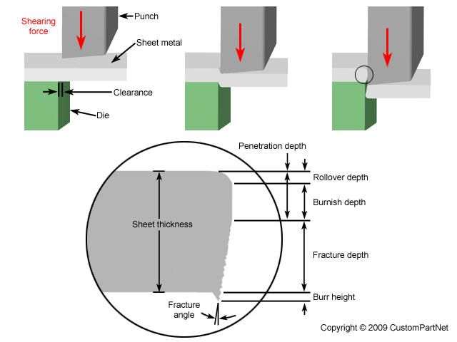
Cutting processes are those in which a piece of sheet metal is separated by applying a great enough force to caused the material to fail. The most common cutting processes are performed by applying a shearing force, and are therefore sometimes referred to as shearing processes. When a great enough shearing force is applied, the shear stress in the material will exceed the ultimate shear strength and the material will fail and separate at the cut location. This shearing force is applied by two tools, one above and one below the sheet. Whether these tools are a punch and die or upper and lower blades, the tool above the sheet delivers a quick downward blow to the sheet metal that rests over the lower tool. A small clearance is present between the edges of the upper and lower tools, which facilitates the fracture of the material. The size of this clearance is typically 2-10% of the material thickness and depends upon several factors, such as the specific shearing process, material, and sheet thickness.

The effects of shearing on the material change as the cut progresses and are visible on the edge of the sheared material. When the punch or blade impacts the sheet, the clearance between the tools allows the sheet to plastically deform and "rollover" the edge. As the tool penetrates the sheet further, the shearing results in a vertical burnished zone of material. Finally, the shear stress is too great and the material fractures at an angle with a small burr formed at the edge. The height of each of these portions of the cut depends on several factors, including the sharpness of the tools and the clearance between the tools.

 
Sheared edge

A variety of cutting processes that utilize shearing forces exist to separate or remove material from a piece of sheet stock in different ways. Each process is capable of forming a specific type of cut, some with an open path to separate a portion of material and some with a closed path to cutout and remove that material. By using many of these processes together, sheet metal parts can be fabricated with cutouts and profiles of any 2D geometry. Such cutting processes include the following:

  • Shearing - Separating material into two parts
  • Blanking - Removing material to use for parts
  • Conventional blanking
  • Fine blanking
  • Punching - Removing material as scrap
  • Piercing
  • Slotting
  • Perforating
  • Notching
  • Nibbling
  • Lancing
  • Slitting
  • Parting
  • Cutoff
  • Trimming
  • Shaving
  • Dinking

Punching

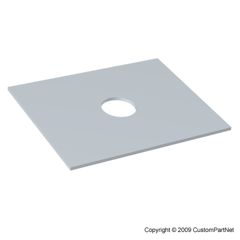
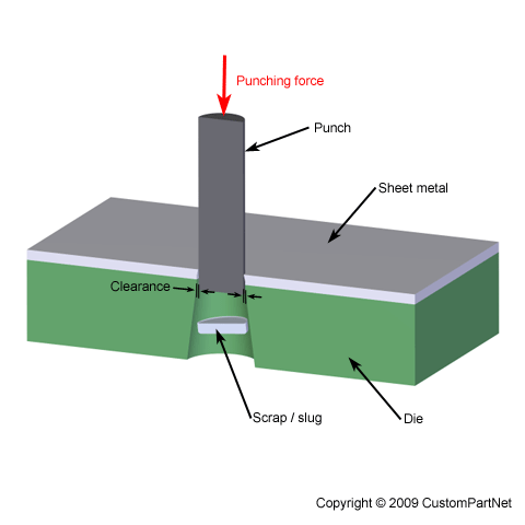
Punching is a cutting process in which material is removed from a piece of sheet metal by applying a great enough shearing force. Punching is very similar to blanking except that the removed material, called the slug, is scrap and leaves behind the desired internal feature in the sheet, such as a hole or slot. Punching can be used to produce holes and cutouts of various shapes and sizes. The most common punched holes are simple geometric shapes (circle, square, rectangle, etc.) or combinations thereof. The edges of these punched features will have some burrs from being sheared but are of fairly good quality. Secondary finishing operations are typically performed to attain smoother edges.

The punching process requires a punch press, sheet metal stock, punch, and die. The sheet metal stock is positioned between the punch and die inside the punch press. The die, located underneath the sheet, has a cutout in the shape of the desired feature. Above the sheet, the press holds the punch, which is a tool in the shape of the desired feature. Punches and dies of standard shapes are typically used, but custom tooling can be made for punching complex shapes. This tooling, whether standard or custom, is usually made from tool steel or carbide. The punch press drives the punch downward at high speed through the sheet and into the die below. There is a small clearance between the edge of the punch and the die, causing the material to quickly bend and fracture. The slug that is punched out of the sheet falls freely through the tapered opening in the die. This process can be performed on a manual punch press, but today computer numerical controlled (CNC) punch presses are most common. A CNC punch press can be hydraulically, pneumatically, or electrically powered and deliver around 600 punches per minute. Also, many CNC punch presses utilize a turret that can hold up to 100 different punches which are rotated into position when needed.

 
Punching

A typical punching operation is one in which a cylindrical punch tool pierces the sheet metal, forming a single hole. However, a variety of operations are possible to form different features. These operations include the following:

  • Piercing - The typical punching operation, in which a cylindrical punch pierces a hole into the sheet.
Piercing
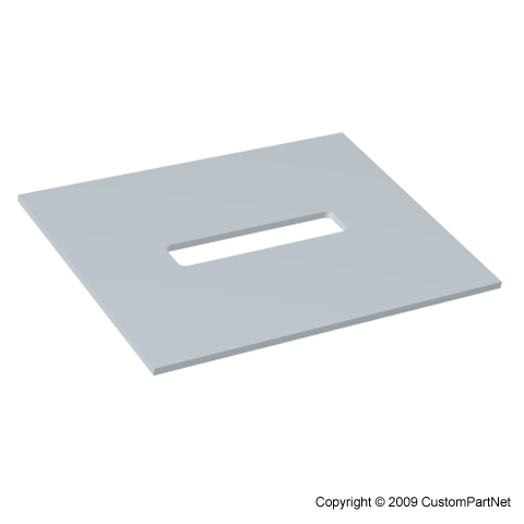
  • Slotting - A punching operation that forms rectangular holes in the sheet. Sometimes described as piercing despite the different shape.
Slotting
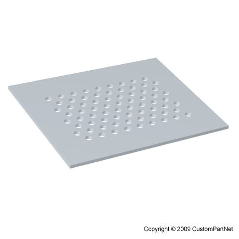
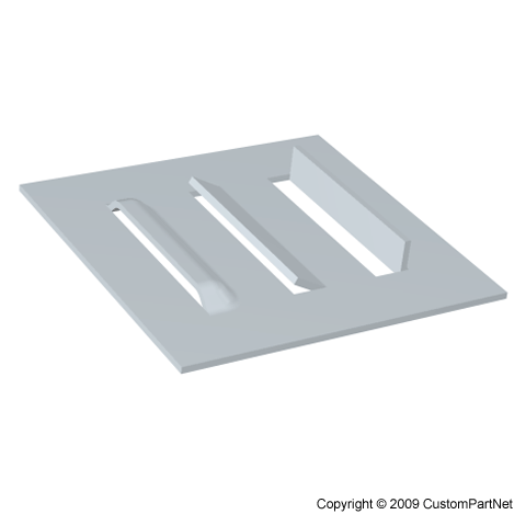
  • Perforating - Punching a close arrangement of a large number of holes in a single operation.
Perforating
  • Notching - Punching the edge of a sheet, forming a notch in the shape of a portion of the punch.
Notching
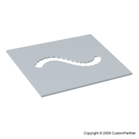
  • Nibbling - Punching a series of small overlapping slits or holes along a path to cutout a larger contoured shape. This eliminates the need for a custom punch and die but will require secondary operations to improve the accuracy and finish of the feature.
Nibbling
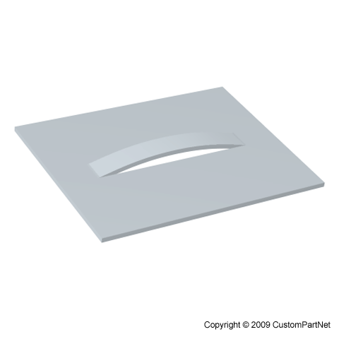
  • Lancing - Creating a partial cut in the sheet, so that no material is removed. The material is left attached to be bent and form a shape, such as a tab, vent, or louver.
Lancing
  • Slitting - Cutting straight lines in the sheet. No scrap material is produced.
Slitting
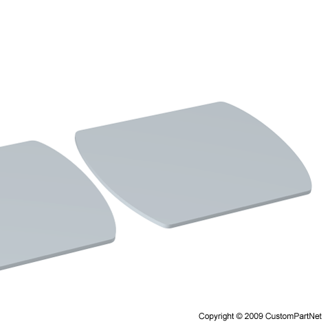
  • Parting - Separating a part from the remaining sheet, by punching away the material between parts.
Parting
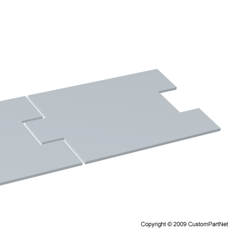
  • Cutoff - Separating a part from the remaining sheet, without producing any scrap. The punch will produce a cut line that may be straight, angled, or curved.
Cutoff
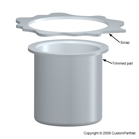
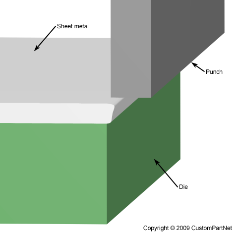
  • Trimming - Punching away excess material from the perimeter of a part, such as trimming the flange from a drawn cup.
Trimming
  • Shaving - Shearing away minimal material from the edges of a feature or part, using a small die clearance. Used to improve accuracy or finish. Tolerances of ±0.001 inches are possible.
Shaving
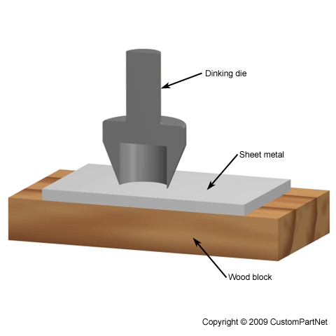
  • Dinking - A specialized form of piercing used for punching soft metals. A hollow punch, called a dinking die, with beveled, sharpened edges presses the sheet into a block of wood or soft metal.
Dinking

Blanking

Blanking is a cutting process in which a piece of sheet metal is removed from a larger piece of stock by applying a great enough shearing force. In this process, the piece removed, called the blank, is not scrap but rather the desired part. Blanking can be used to cutout parts in almost any 2D shape, but is most commonly used to cut workpieces with simple geometries that will be further shaped in subsequent processes. Often times multiple sheets are blanked in a single operation. Final parts that are produced using blanking include gears, jewelry, and watch or clock components. Blanked parts typically require secondary finishing to smooth out burrs along the bottom edge.

The blanking process requires a blanking press, sheet metal stock, blanking punch, and blanking die. The sheet metal stock is placed over the die in the blanking press. The die, instead of having a cavity, has a cutout in the shape of the desired part and must be custom made unless a standard shape is being formed. Above the sheet, resides the blanking punch which is a tool in the shape of the desired part. Both the die and punch are typically made from tool steel or carbide. The hydraulic press drives the punch downward at high speed into the sheet. A small clearance, typically 10-20% of the material thickness, exists between the punch and die. When the punch impacts the sheet, the metal in this clearance quickly bends and then fractures. The blank which has been sheared from the stock now falls freely into the gap in the die. This process is extremely fast, with some blanking presses capable of performing over 1000 strokes per minute.
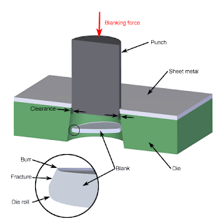
 
Blanking

Fine blanking

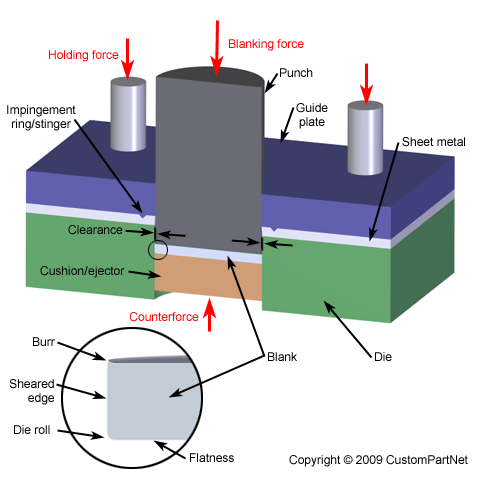
Fine blanking is a specialized type of blanking in which the blank is sheared from the sheet stock by applying 3 separate forces. This technique produces a part with better flatness, a smoother edge with minimal burrs, and tolerances as tight as ±0.0003. As a result, high quality parts can be blanked that do not require any secondary operations. However, the additional equipment and tooling does add to the initial cost and makes fine blanking better suited to high volume production. Parts made with fine blanking include automotive parts, electronic components, cutlery, and power tools.

Most of the equipment and setup for fine blanking is similar to conventional blanking. The sheet stock is still placed over a blanking die inside a hydraulic press and a blanking punch will impact the sheet to remove the blank. As mentioned above, this is done by the application of 3 forces. The first is a downward holding force applied to the top of the sheet. A clamping system holds a guide plate tightly against the sheet and is held in place with an impingement ring, sometimes called a stinger, that surrounds the perimeter of the blanking location. The second force is applied underneath the sheet, directly opposite the punch, by a "cushion". This cushion provides a counterforce during the blanking process and later ejects the blank. These two forces reduce bending of the sheet and improve the flatness of the blank. The final force is provided by the blanking punch impacting the sheet and shearing the blank into the die opening. In fine blanking, the clearance between the punch and the die is smaller, around 0.001 inches, and the blanking is performed at slower speeds. As a result, instead of the material fracturing to free the blank, the blank flows and is extruded from the sheet, providing a smoother edge.

 
Fine blanking

Shearing

As mentioned above, several cutting processes exist that utilize shearing force to cut sheet metal. However, the term "shearing" by itself refers to a specific cutting process that produces straight line cuts to separate a piece of sheet metal. Most commonly, shearing is used to cut a sheet parallel to an existing edge which is held square, but angled cuts can be made as well. For this reason, shearing is primarily used to cut sheet stock into smaller sizes in preparation for other processes. Shearing has the following capabilities:
  • Sheet thickness: 0.005-0.25 inches
  • Tolerance: ±0.1 inches (±0.005 inches feasible)
  • Surface finish: 250-1000 μin (125-2000 μin feasible)

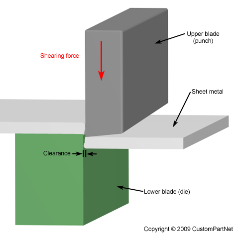
The shearing process is performed on a shear machine, often called a squaring shear or power shear, that can be operated manually (by hand or foot) or by hydraulic, pneumatic, or electric power. A typical shear machine includes a table with support arms to hold the sheet, stops or guides to secure the sheet, upper and lower straight-edge blades, and a gauging device to precisely position the sheet. The sheet is placed between the upper and lower blade, which are then forced together against the sheet, cutting the material. In most devices, the lower blade remains stationary while the upper blade is forced downward. The upper blade is slightly offset from the lower blade, approximately 5-10% of the sheet thickness. Also, the upper blade is usually angled so that the cut progresses from one end to the other, thus reducing the required force. The blades used in these machines typically have a square edge rather than a knife-edge and are available in different materials, such as low alloy steel and high-carbon steel.

 
Shearing