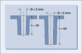
| Holes are easily produced in molded parts by core pins. Through holes are easier to produce than blind holes because the core pin can be supported at both ends. |
| Blind holes |
| Core pins supported by just one side of the mold tool create blind holes. The length of the pins, and therefore the depth of the holes, are limited by the ability of the core pin to withstand any deflection imposed on it by the melt during the injection phase. See information on bosses & cores. As a general rule the depth of a blind hole should not exceed 3 times the diameter. For diameters less than 5 mm this ratio should be reduced to 2. Blind cores. |
| Through holes |
| With through holes the cores can be longer as the opposite side of the mold cavity can support them. An alternative is to use a split core fixed in both halves of the mold that interlock when the mold is closed. For through holes the length of a given size core can be twice that of a blind hole. In cases where even longer cores are required, careful tool design is necessary to ensure balanced pressure distribution on the core during filling to limit deflection. Through cores. |
| Holes with an axis that runs perpendicular to the mold opening direction require the use of retractable pins or split tools. In some designs placing steps or extreme taper in the wall can avoid this. See section on draft. Core pins should be draw polished and include draft to help with ejection. The mold design should direct the melt flow along the length of slots or depressions to locate weld lines in thicker or less critical sections. If weld lines are not permissible due to strength or appearance requirements, holes may be partially cored to facilitate drilling as a post molding operation. The distance between two holes or one hole and the parts edge should be at least 2 times the part thickness or 2 times the hole diameter whichever is the largest. Minimum hole spacing dimensions. |
| For blind holes the thickness of the bottom should be greater than 20% of the hole diameter in order to eliminate surface defects on the opposite surface. A better design is to ensure the wall thickness remains uniform and there are no sharp corners where stress concentrations can occur. Blind hole design recommendations. |
This blog is about component analysis, injection mold design and construction, mold manufacturing, defects and remedies, mold parameters,Tool design etc,.


No comments:
Post a Comment